Step 1
This step will show you the various LEDs that are on the half-sized line follower.
The picture below shows the 3 LEDs that can be controlled.
It also shows the button, which can be used by your program
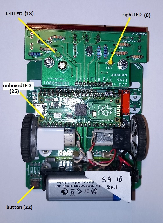 |
The LEDs have been given names you can use in your program.
The numbers in brackets are used to choose which Pi Pico input/output pin we are talking about. |
do this at the start of your program
# digital outputs
onboardLED = Pin(25, Pin.OUT) #beware of case
leftLED    = Pin(13, Pin.OUT) # sensor board left LED
rightLED   = Pin(8, Pin.OUT)  # sensor board right LED
But what is a "Pin"?
At the very start of your program you must "import" the definition of a Pin from the "machine"
You will be using time delays , so you need to import time as well:
import time       #used for time delays
from machine import Pin
This is the python code for turning on an LED.
Do this in your program, when you want it to go on.
onboardLED.value(1) #switch on
And for turning off
onboardLED.value(0) #switch off
This while loop turns them on and off repeatedly
#test the LEDs
while True: #loop forever
    onboardLED.value(1)    # turn it on
    time.sleep(1)          # wait 1 second
    onboardLED.value(0)    # turn it off
    time.sleep(1)          # wait 1 second
So here is the complete program:
# St Albans UKMARS classroom buggy
# started 09/07/2023
# Half size sensor board
# drv8833 motor driver
import time
from machine import Pin

# digital outputs
onboardLED = Pin(25, Pin.OUT) #beware of case
leftLED = Pin(13, Pin.OUT)# sensor board left LED
rightLED = Pin(8, Pin.OUT)# sensor board right LED
pcbLED = Pin(21, Pin.OUT) # pcb LED (recent boards do not have one)

#test the LEDs
while True: #loop forever
    onboardLED.value(1)
    time.sleep(1)
    onboardLED.value(0)
    time.sleep(1)

'''
EXTENSIONS
Try all the LEDs,
Test smallest delay to still see flashing,
Light several LEDs in sequence.
'''
Step 2
This step will show you the line sensors for the half-sized line follower.
The picture below shows the Trigger LEDs that are needed for line sensing.
It also shows the two light sensors, which detect the line.
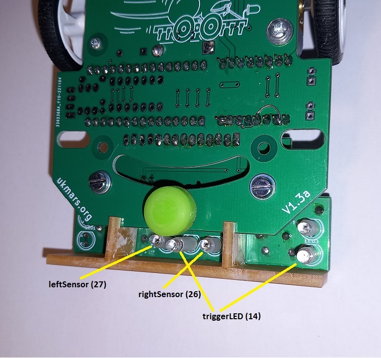 |
The 2 LEDs are both controlled from the same Pin.
The sensor with no name on the right is the stop sensor we will come to that later |
This is the python code you need to set up the names of the LED and sensors.
do this at the start of your program
triggerLED = Pin(14, Pin.OUT)# needed for sensing the line
#analogue inputs
rightSensor = ADC(26)
leftSensor  = ADC(27)
But what is an "ADC"?
At the very start of your program you must "import" the definition of an ADC from the "machine"
This is in addition to the Pin, and time.
An ADC is an Analogue to Digital Convertor.
import time       #used for time delays
from machine import Pin , ADC
This is the python code for turning on the trigger illumination LED.
Do this in your program, when you want it to go on.
triggerLED.value(1) #switch on