Basic sensor commands
Useful websites to
learn more about BASIC commands and what they mean
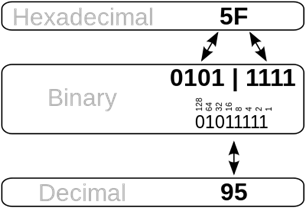
Binary conversion
|
Watch video https://www.youtube.com/watch?v=ewokFOSxabs Play game https://studio.code.org/projects/applab/iukLbcDnzqgoxuu810unLw
|
Basic stuff that you
need to know
|
|
||
|
|
||
|
|
||
|
|
||
|
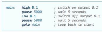
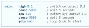
Setting pins |
||
|
|
||
|
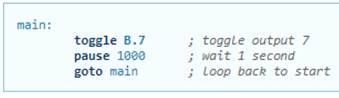
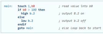
Toggling pins |
||
|
|
||
|
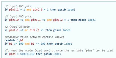
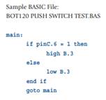
If statements |
||
|
|
||
|
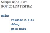
Reading
analogue values |
||
|
|
||
|
Pause |
||
|
|
||
|
|
||
|
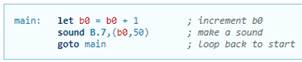
Playing sounds |
||
|
|
||
|
Reading switch |
||
|
||
|
Piezo sounder |
||
|
||
|
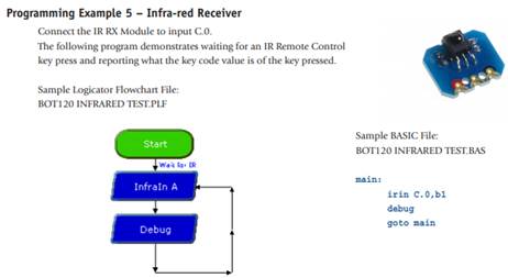
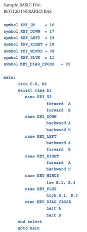
Infrared receiver |
||
|
|
||
|
LDR (Light sensor) - Analogue reading |
||
|
||
|
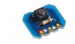
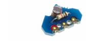
Touch sensor |
||
|
|


Basic vs Python
comparison
|
BASIC |
PYTHON |
|
Assignment |
|
|
let pins = %10101111 |
pins = %10101111 |
|
Comparison |
|
|
|
|
|
If statements (selection/decisions) |
|
|
if condition then *do this* end if |
if C.1 > %10101111 : b7 = 500 |
|
If… else |
|
|
if condition then *do this* else *do this* end if |
if condition : *do this* else: *do this* |
|
If… elseif… else |
|
|
if condition then *do this* elseif condition then *do this* elseif condition then *do this* else end if |
if condition : *do this* elif condition : *do this* elif condition : *do this* else: *do this* |
|
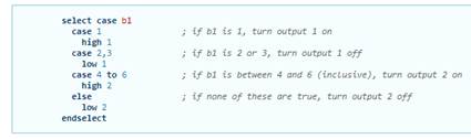
Select case statements |
|
|
|
|
|
For loops (count controlled) |
|
|
|
for i
in range(1,20): if
pinC.1 == 1: break |
|
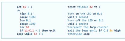
While loops (condition controlled loops) |
|
|
|
while pinC1 == 1 : *do this* |
|
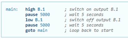
Forever loops (infinite loops) |
|
|
|
while True: *do this* |
|
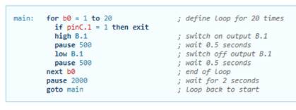
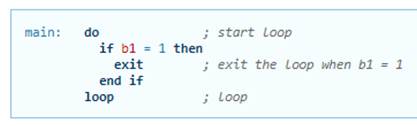
Exiting from a forever loop (the exit command) |
|
|
|
while True: *do this* if condition : break |
|
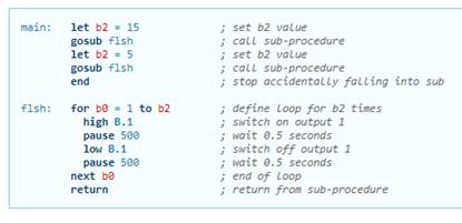
Subroutines |
|
|
|
flash() flash() def flash(): high B.1 pause 500 |
|
Delay |
|
|
|
import time time.sleep(1000) |

Tasks
|
1: Light LED with pauses. |
|
LED on/off pin B.3 (there's also an LED on B2) (flash on / off - pause) Choose pause time. BOT115 example 1 page 16, flashes 2 LEDs alternately. |
|
2: Push button + LED |
|
See BOT115 example 2, Page 17. - LED on/off pin B.3 - if pin c.1 =1 (decision) - push for on, push again for off - long press for flash. Extension : detect long press, and give slow flashes. |
|
3: LDR + LED |
|
Read analogue voltage - debug LDR on B.1 - flash LED with speed depending on LDR ( pause length) - potentiometer on C.2 - > debug. Use potentiometer to set threshold for light alarm. readadc B.1,B0 readadc C.2,B1 if B0 > B1 then ..... |
|
4 Piezo B.5 |
|
- "sound" command with pitch/duration. - "play" command (4 tunes built-in) - piezo pitch depends on LDR light level. Extra 1: make piezo play by manually pulsing high, then low. See what toggle does with no delays on loop. Extra 2: Simple loop with toggle. BUT. Run with different processor speeds! Use setfreq m4 for normal, up to setfreq m32. 8 times faster. |
|
5 TV remote + piezo. B.0 |
|
- select tune to "play" based on digit pressed. - enter 2 digit number for "sound" command. |
|
6 Virtual pet |
|
If you cuddle it, it purrs (buzzer) - temp sensor to detect cuddle C.6 - pulsed buzzing for purring. B.4 purr purr....purr purr....purr purr....purr purr.... |
|
7 Fridge alarm |
|
- temp sensor C.6 - LDR B.1 - buzzer. B.4 Buzzes if it gets too warm. Buzzes if door open (light) for too long. |
|
8 Parking distance sensor |
|
- Sharpe single analogue input. C.2 - sound buzzer more quickly as you get closer. B.4 - sound continuously when too close. B.4 Use analogue signal to calculate distance in cms. Dist = 13 / signal voltage in volts. See https://www.smart-prototyping.com/blog/Sharp-Distance-Measuring-Sensor-GP2Y0A41SK0F-Tutorial Use maths to calculate pauses, and a decision as to when to make it continuous. |
|
9 Debug techniques. |
|
- send message back up the download lead on power up sertxd("This is BOT115 example 2a",13,10) - debug screen to see all your data items debug |
|
10 Stationary Line Follower |
|
Control 1 motor using pins B.6,B.7 Read a line position sensor on C.2. Mount the motor and the line sensor so that the rotation of the motor shifts the sensor sideways. Your program should stop the motor if the sensor is central (120) within a margin of +- 20. If > 140 then drive the motor forwards. If < 100 then drive the motor backwards. OR maybe the other way round, depending on the electrical connection to the motor, or mechanical arrangement. Enhancement: make the line signal be corrected according to speed of change (or Derivative) Corrected = (this reading - previous) * Constant + this reading. Then use corrected signal instead of this reading. So that it stops earlier if it's already heading towards the centre. Use a mechanical linkage to drive it nearer/further from the wall. |
|
11:Stationary Wall Follower |
|
Control 1 motor using pins B.6,B.7 Read wall distance sensor on C.2. |
|
Line following techniques |
|
Line Following Techniques ======================= There are a large number of engineering considerations involved in Line following. Sensor options TCRT5000, (height control above baseboard) Hamamatsu sensors (4 digital) Adjusting Hamamatsu LEDs QTR sensors ( 4 gang, 6-gang) 1 Digital sensor (Crossing problem/ 2 zones) 2 Digital sensors (inside / line, 5 zones) 3 Digital sensors (7 digital zones) "Weighted Average" analogue position calculation. Analogue sensor dark/light calibration. Intelligent sensor. 3-zone (2 decision thresholds to set motor speeds) 5-zone (4 thresholds) "select" in BASIC. Use of High, Low, and Toggle BASIC. "Fallen-off" detection /options Variable speed motors ( 32 zones) Maths to calculate motor speeds Proportion Derivative Speed controlled by curvature (sensor reading/zone) Speed reduction (/zero) on fall-off Sensor position - distance ahead of wheels TV remote to tune values Tuning on the fly EEPROM store for data ___________________________________________________________ Details: TCRT5000 a small infra-red LED/ IR receiver that senses white insulating tape against a blackboard paint background. It provides an analogue output reading from 50-60 for black, to 230 odd for white at a distance of 9mm. BASIC "readadc" The reading needs the backgrond value (black) subtracted from the value, before it can be used in weighted-average calculation of line position. It is simpler to simply use it as a digital sensor: on the line or off. Hamamatsu this is a white light optical sensor that also controls (modulates) the illumination LED(s). It correlates the sensor reading against the illumination pattern to give positive indication of "white" Digital only, but can be used with a single sensor and multiple LEDs to provide up to 6 detection zones. It can only give a digital yes/no, and requires extra hardware and some software/ output ports, to run with multiple LEDs. Used in original Wham! robots. BASIC : complex subroutine. Intelligent sensor this uses 3 TCRT5000 sensors spaced 10 mm apart to detect the position over a 19mm white tape. It uses an 08M2 Picaxe chip to process the 3 analogue signals to a single analogue output. It uses the reducing analogue outputs profile as each sensor passes over the tape to calculate a number in the range 0-31. The DAC output from the 08M2 restricts the granulatity. Proportion The speeds for each motor are calculated from the formulae: BaseSpeed + Kp* (sensorPosition- centre value) (right motor) BaseSpeed - Kp* (sensorPosition- centre value) (left motor) where Kp is the proportional coefficiant Derivative This is intended to increase stability. The instability is caused by the time delay between sensing the position over the line and the speed changes actually resulting from the changes in motor voltages. The technique requires storing the sensor reading from a previous sample (10 ms or so) and combining that with the current reading, to calculate a future reading.
Mr Fisher 12/11/2019 |
|
Intelligent line sensor |
|
About the intelligent sensor.txt This sensor uses 3 Infra Red detectors (TCRT5000) to measure its position on a white line. It produces an analogue value (in the range 0 - 230) to show where it is. ---- 0 is at the very left, or fallen off the left hand side. 230 is at the very right, or fallen off the right hand side. 110 is the middle of the line. (approximately) ---- The sensor has 3 connections, Ground, Power and Output. The connector has 5 pins pointing downward. From the left hand side; 1: +5 volts power 2: not connected 3: not connected 4: Output 0-5volts 5: Ground 0 Volts. ---- When you switch on, you should "show" it the line. It needs to measure the blackness of the background, and the whiteness of the line.
Switch on with the sensor to the left of the line. Slowly drag the sensor across to the line, and continue till it is to the right of the line. You can use the Analogue Output to steer your robot so that it follows the line. Subtract the center value (110) from the Output and you have a number that is zero in the middle, positive to the right, and negative to the left. You need to multiply this number by a fraction - say 10/50 to reduce it so that the robot doesn't over-steer. Then add this to the speed of the right wheel, and subtract it from the speed of the left wheel, and the robot should steer appropriately. WARNING: Picaxe basic doesn't do negative numbers. So do the *10/50 on the reading, before subtracting 110 * 10/50 (=22) from the result. Actually it does do negative numbers but they are indistinguishable from large positive numbers. Effectively it adds enough 256s to bring it positive again. Consider: 7-9 gives 254 which is 256-2. 254 works as -2 when you add it to something. 10 + 254 gives 8. That's because, if the answer is greater than 255 it subtracts 256 until it is <256. Look up "modular arithmetic" |