Step 4
So far we have been outputting signals to Pins as 0 or 1: ON that is OFF
This step shows how to output a variable signal between 0 and 1.
A signal that can dim an LED gradually, or drive a motor at different speeds.
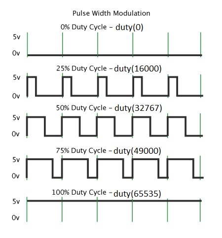 |
The output is actually always 0 or 1.
It is automatically switched between the two with a ratio which Pico program controls with the duty() method of the PWM output. |
do this at the start of your program
# digital outputs
onboardLED = PWM(Pin(25))
leftLED    = PWM(Pin(13))
rightLED   = PWM(Pin(8))
Having set up the outputs you also have to set up the speed at which the pulses go on and off
# digital outputs
onboardLED.freq(1000)
leftLED.freq(1000)
rightLED.freq(1000)
This is because of the PWM frequency is within the audible range
Finally the program needs to set the proportion of time the PWM signal is on or off
this is called the duty ratio, and is controlled by the PWM's duty_u16() method.
# digital outputs
onboardLED.duty_u16(0)   # this will turn the LED off
leftLED.duty_u16(32760)  # half brightness
rightLED.duty_u16(65525) # full brightness
Step 4a
This step shows how to drive the motors at different speeds.
Also, how to drive them backwards.
current to flow forwards, or backwards through the motor,(at the centre).
 |
The motor is fed via four transistors.
These are labelled fwd and rev in the diagram. If both fwd ones are on then the motor goes forwards. If both rev ones are on then the motor goes backwards. |
#*********  PWM Outputs ******************
leftRev  = PWM(Pin(9))
leftFwd  = PWM(Pin(11))
rightRev = PWM(Pin(10))
rightFwd = PWM(Pin(12))
Also set the freq() for each to be 1000
#setup left and right motor PWM frequency
leftRev.freq(1000)
leftFwd.freq(1000)
rightRev.freq(1000)
rightFwd.freq(1000)
Then you need to set the duty ratio, of the fwd and rev PWM outputs
according to the speed (forwards or backwards) you want for the motor.
Full speed ahead
# PWM outputs
leftRev.duty_u16(0)
leftFwd.duty_u16(65525)  #

rightRev.duty_u16(0)
rightFwd.duty_u16(65525) # full speed forwards
Half speed backwards
# PWM outputs
leftRev.duty_u16(32767)  # half speed backwards
leftFwd.duty_u16(0)      # off

rightRev.duty_u16(32767) # half speed backwards
rightFwd.duty_u16(0)     # off